Almost every premature heating-element failure traces back to a specification written in the wrong order. The kilowatt figure gets decided first — because that is what the process engineer knows — and then everything else is bent to fit it. Reverse the order and the failures mostly disappear.
1. Name the medium
The medium decides more than any other single input. Air, water, mineral oil, cooking oil, molten nitrate salt, caustic solution and plating chemistry each remove heat at different rates and attack different alloys. A heater that is correct in one is destroyed in another, which is why the same physical geometry is cataloged under different series codes for different media.
Be specific. "Oil" is not enough — mineral oil, thermal-transfer fluid, quench oil and vegetable frying oil have different film-temperature limits, and the safe watt density follows the fluid rather than the tube.
2. State both temperatures
Two numbers matter and they are frequently confused. The medium temperature is what your process runs at. The sheath temperature is what the tube surface reaches, and it is always higher. Catalog ratings are quoted on medium temperature so you can size from your set-point directly — but the sheath is what actually fails, and the gap between the two is set by watt density.
3. Set the watt density from the medium
Watt density — watts per square centimetre of heated surface — is the number that decides service life. Every medium has a ceiling above which the fluid touching the sheath degrades faster than it can carry heat away.
4. Choose the sheath from the chemistry
Sheath alloy follows what the medium does chemically, not how hot it is. Nitrate salt attacks carbon steel and wants stainless; hot caustic is better served by carbon steel; chlorides pit stainless and want titanium; strong acids eat titanium and want PTFE. Getting this wrong is the second most common specification error after watt density, and it shows up as pitting along the liquid line within months rather than as a sudden failure.
5. Fix the mounting and the seal
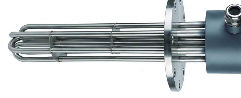
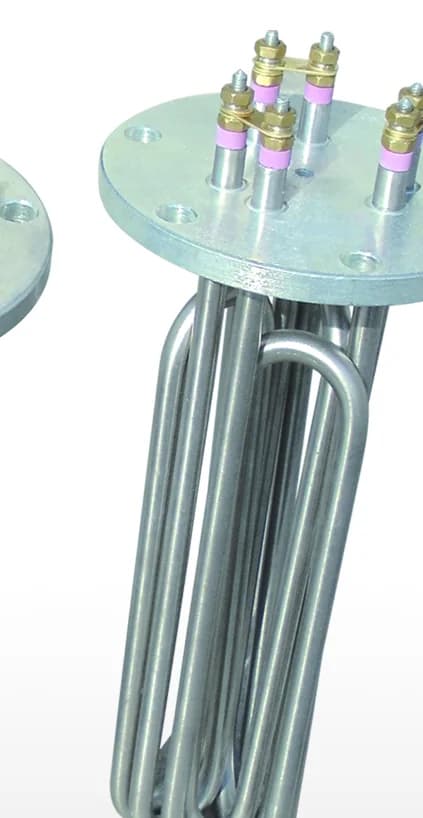
If the element passes through a pressure boundary, the mounting is a pressure part. A machined flange with a gasket face handles 0.8–4 MPa; a threaded boss with a sealing washer handles lower duties in smaller vessels. Send the flange standard you work to — DIN, ANSI, JIS or GB — rather than a bolt-hole count, and the mating face will be cut to match instead of adapted afterwards.
6. Confirm the supply, then let the kilowatts fall out
Voltage and phase are usually fixed by the site: 36, 55 or 110 V for safety extra-low-voltage equipment, 220 V single phase, 380 V three phase. Only now calculate the power — from the mass to be heated, the temperature rise, the time available and the standing losses. If that number cannot be delivered at the safe watt density in the space available, the answer is more surface area (a longer element, a larger bundle, or fins), never a hotter tube.
Preguntas frecuentes
What is the single most common mistake in specifying a heating element?
Fixing the kilowatts first and forcing everything else to fit. Power should be the output of the calculation, not its input. When the required load will not fit at a safe watt density, the correct response is to add surface area — a longer element, more elements, or fins — rather than to accept a higher density and a heater that fails in months.
Is medium temperature or sheath temperature the rating I should design to?
Design to medium temperature, because that is your process set-point and it is what catalog ratings are quoted against. But understand that the sheath always runs hotter, and the gap between the two is set by watt density — which is why the density table matters more than the temperature rating.
How much detail do you need to size a heater properly?
The medium by name, the mass or flow rate, the starting and target temperature, the time allowed, the supply voltage and phase, the mounting arrangement, and the vessel's design pressure if there is one. Standing heat loss matters for anything that holds temperature rather than just raising it.